|
Technical Description
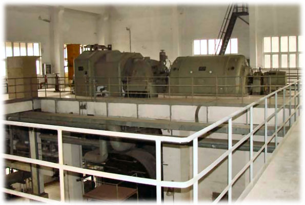
The referred gas turbine unit generates electricity by using gas-fired engine. The gas turbine unit was manufactured by General Electric (“GE”) of the United States. The model of the unit is LM6000PA, which is a Simple Cycle Gas Turbine Unit by adapting to dual fuel, gas and/or 0# diesel oil, with a rated power generating capacity of 42MW.
The gas turbine unit is a Model LM6000PA air-derivative power generating system, which is made by GE. The generator is made by Brush Company. The operating set was manufactured by the original S&S Company, whose business unit was acquired by GE sometime ago. The turbine/generator operating unit was put into operation in December 1995. The gas fuel conversion project was completed at the end of 2004. The total power generating hours for the operating unit were about 11,000 hours; among which there about 3200 hours is operated by using gas as the fuel. The number of starts is more than 1940.
The unit was transported back to GE Huston base for maintenance purposes at the end of 2004. The new combustor which can use either gas or diesel oil as fuel, HPT and LPT were all installed into the system. The service and product bulletin at the end of 2004 by GE were also implemented. The equipment is in good operational condition.
The operating company has made strict daily and periodical maintenance regulations for the units, which is in line with the operational procedures established by GE.
The unit is equipped with the Air Inlet chilling/heating system, which adjusts the temperature of the gas to the standard criterion during summers. The unit would be heated up by a boiler in winters to avoid icing conditions within the system. The operation hour for the device is about 2800 hours. The device is comprehensively maintained each year. The last such maintenance was completed in May 2008.
The gas system is equipped with a set of fuel gas boosting compressor unit, which mainly is used for boosting gas pressure from 0.85 MPA to about 4.6 MPA; with a rated flux of 12,000 standard squares per hour. The operation hour for the device is about 3200 hours. The device is particularly maintained each year. The device performs well presently and it is in good operating condition.
Major components of LM6000 gas turbine generator set
- One outdoor weatherproof enclosed skid mounted LM6000 GT packaged with one 55 MVA Generator.
- Dual Fuel of Diesel and Natural Gas. Duplex Fuel Centrifuge (100% standby) Module for diesel treatment.
- Generator (See Item 1 above).
- Duplex liquid fuel filter skid complete with fuel pre-heating capability. Air Inlet chilling/heating system include:
1) Chiller/heating coils for GT air inlet Module
2) Qty 2 –1000 ton centrifugal chiller compressors-380V
3) Air management skid to include pumps controls and heat exchanger for heating boiler. |
- Gear Box is reduced from 3600 rpm to 3000rpm.
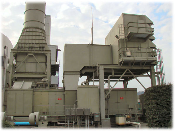
- Simple cycle exhaust system include:
1)Diverter Box(excluding Blade and Actuator).
2)Transition duct and expansion joints.
3) Silencer.
4) Support structure.
5) 24 Meter exhaust stack.
|
- Auxiliary facilities Skid.
- Lube oil reservoir heater for GT and Gearbox/Generator.
- Duplex liquid fuel boost pump skid.
- MH62 fuel gas boosting compressor unit.
- Duplex Fuel Centrifuge (100% standby) Module.
- CO2 fire fighting skid.
- Air compressor skid.
- Air intake cooling and anti-frozen device (See Item 4 above).
- Modular control room outdoor weatherproof enclosed to include:
1) Basic house.
2) Turbine control.
3) 15KV switchgear.
4) Relay panel.
5) 400V MCC etc.
|
Technical Specifications
| Item |
Equipment |
Manuf. |
Type |
Serial No. |
Parameters |
| 1 |
Gas Turbine |
GE |
LM6000PA |
185-142 |
3600 rpm of L.P. compressor
10200 rpm of H.P. compressor
27-68 PSIG Lube oil supply pressure
20-80 PSIG Lube oil supply pressure |
| 2 |
Generator |
BRUSH |
BDAX7-290ERJ |
62106A-2C |
0.8 power factor
13.8KV outlet voltage
50Hz @ 3000 rpm 3 phase
Coupling:Zurn, type
Model:23-10 |
| 3 |
Hydraulic starter system |
|
|
|
40 gal Oil Tank volume
hydraulic filter: 10µm
25PSIG bypass pressure:
12gpm@350Psig Oil filling pump
56gpm@5200Psig Circulating pump |
| 4 |
Air system for venting and flaming |
|
|
|
32400 ACFM - total air flow
230000 ACFM - GT air intake
94000 ACFM – air flow |
| 5 |
Lube oil for GT |
|
|
|
Tank Volume: 150gal
Oil supply filter: 6µm
Oil return filter: 6µm
Cooling: double piping heat exchanger |
| 6 |
GT Hydraulic system |
|
|
|
Rated oil supply pressure: 650Paig
Filter: 15gpm, 1200Psig, 12µm |
| 7 |
Lube oil for Gearbox/Gen |
|
|
|
Tank volume: 3000 L
Filter: 6µm
Cooling: double piping heat exchanger |
| 8 |
Fire protection system |
|
|
|
Fire extinguish ant: CO2
Heat probe detector
Optical flame detector
Inflammable gas detector |
| 9 |
Dual Fuel Diesel & Gas |
|
|
|
1340PSIG – Oil supply pressure
≤1400F – Oil supply temperature
670PSIG – Gas Pressure
M^3 – Rated volume:11000 standard cube |
| 10 |
Gearbox |
Lufkin |
NFVQ2419C |
11848 |
3600 rpm - high speed gear
3000 rpm - low speed gear |
Operational Records
1. Historical records of operation
Year |
1996 |
1997 |
1998 |
1999 |
2000 |
2001 |
2002 |
Operation Hours |
2100 |
1109 |
242 |
214 |
168 |
|
|
Year |
2003 |
2004 |
2005 |
2006 |
2007 |
2008 |
|
Operation Hours |
1628 |
2886 |
1207 |
480 |
861 |
- |
|
Total Hours |
11182 |
Fire starts (times) |
1940 |
2. Main parameters of full-load in the last operation (Start up & Stoppage) (see history record) Date: September 11, 2007
Item |
Content |
Remarks |
Operator |
Ambient Temperature |
Dry Bulb: 26.6 ℃
Wet Bulb: 24 ℃
Humidity: % |
|
|
1st Start |
Start Time:9:08
Synchronizing Time: 9:20
Full Load Time: 9:25 |
|
|
1st Stop |
Unload time:13:06
Trip Time:13:11
Stop Time: 13:40 |
|
|
2nd Start |
Start Time:
Synchronizing Time:
Full Load Time: |
|
|
2nd Stop |
Unload time:
Trip Time:
Stop Time: |
|
|
Generation & Fuel Consumption |
Power Metering From: 4251.98
Fuel Metering From: 17842102 |
|
|
Power Metering to: 4253.85
Fuel Metering to: 17842102 |
Pressure Diff. - Inlet Air |
Combustion-air in:
Circulation-air in: |
|
|
Max Differ T48 |
△T48max ℉ |
|
|
Statistics after GT Stop |
FSLO: 55 FSWM: CDLO: SML: |
|
|
STDI: Peak Value-T3 Hours:
Peak Value-T3 Times: Basic T3: |
Basic T3 times: Cold T3 Hours:
Cold T3 times: |
Start Attempts: 621 No. of Fire Start: 436
Engine Run Time: 3232.8 |
Procedure For Stoppage
Item |
Content |
Remarks |
Operator |
| 1 |
Start air compressor before stoppage of GT. |
|
|
| 2 |
Stop GT. Switch off volt regulator in TCP#2 Cabinet when 52G is on. |
|
|
| 3 |
Cut off fans for GTG. |
|
|
| 4 |
Switch off valve for CO2 fire-fighting. |
|
|
| 5 |
Shut down boiler or chiller. |
|
|
| 6 |
Check that the transformer for chiller is switched off. |
|
|
| 7 |
Check that the oil temperature of chiller. It should be within 145~150℉. |
|
|
| 8 |
Stop AMS pumps. |
|
|
| 9 |
Check and clean the GTG skid and other auxiliary skids. |
|
|
| 10 |
Shut down air compressor after 1.5 hours of GT' stoppage. |
|
|
|